


Description
TECHNICAL DATA SHEET
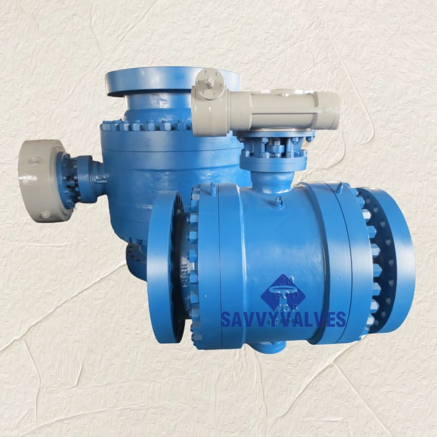
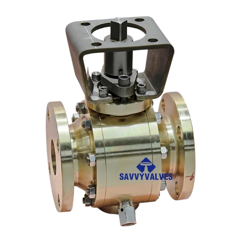
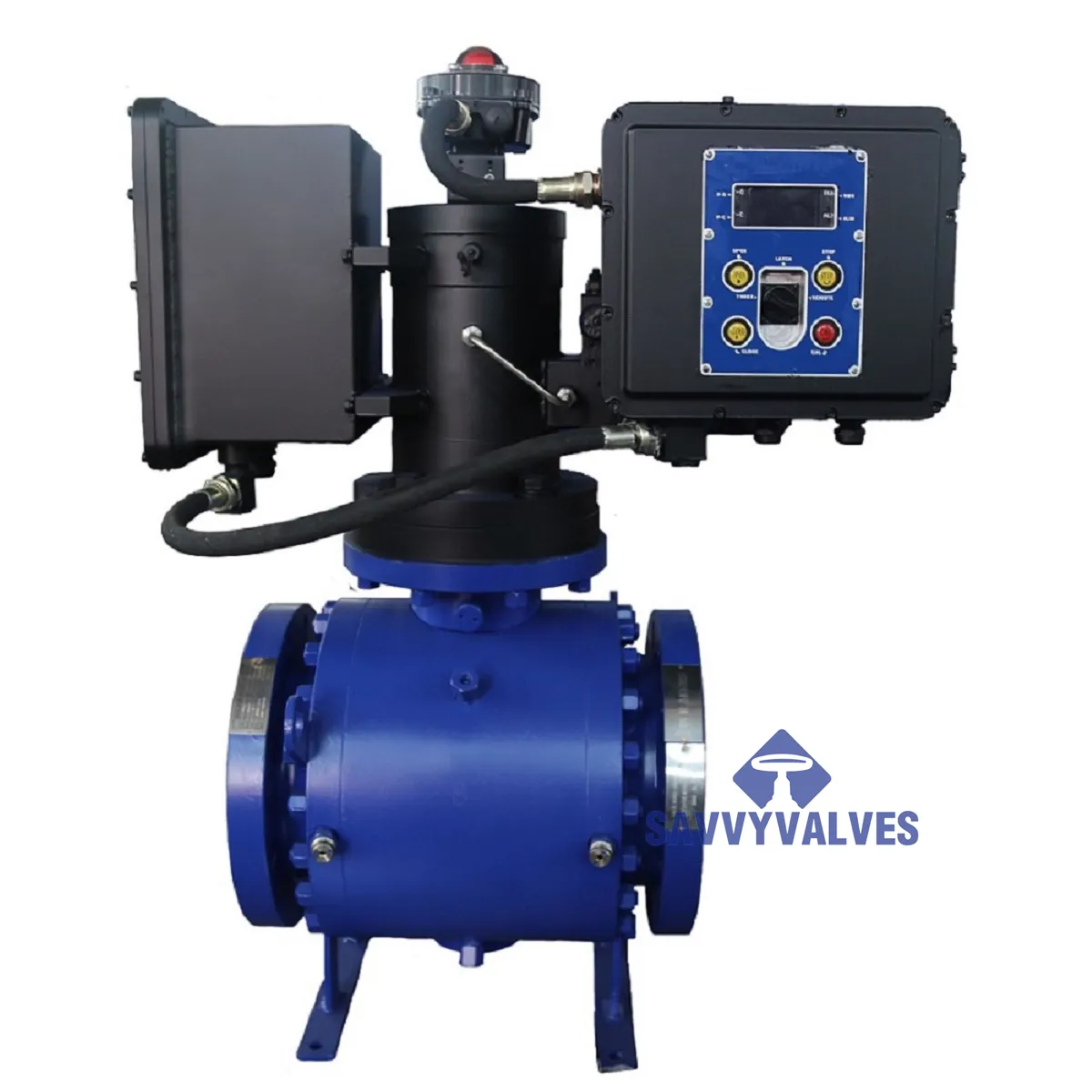
Two-Piece Forged/ Cast Steel Trunnion Mounted Ball Valve
Models: Flanged / Butt Weld, Reduced Bore / Full Bore
This two-piece trunnion-mounted ball valve is engineered for demanding isolation and flow control applications in oil & gas, petrochemical, chemical, power generation, and long-distance pipeline services. Featuring a robust two-piece bolted body construction with fixed ball trunnion design, it provides bidirectional bubble-tight shutoff, reduced operating torque, and extended service life under high pressure and large diameter conditions .
Key Design Features:
|
Item |
Standard / Code |
|
Design & Manufacture |
API 6D, API 608, ASME B16.34, ISO 17292 |
|
Face-to-Face Dimension |
ASME B16.10, API 6D |
|
End Connections |
ASME B16.5 (RF/RTJ), ASME B16.25 (BW), EN 1092-1, MSS SP-44 |
|
Pressure Testing |
API 6D, API 598, ISO 5208 |
|
耐火金庫 |
API 607, API 6FA, ISO 10497, BS 6755 Part 2 |
|
Fugitive Emission |
ISO 15848-1, TA-Luft (optional) |
|
帯電防止 |
BS 5353, ISO 17292 |
|
NACE |
MR0175 / ISO 15156 |
|
SIL Rating |
SIL 3 Capable (IEC 61508) |
|
Quality System |
API 6D Monogram, PED/TPED, ATEX |
|
パラメータ |
仕様 |
|
バルブタイプ |
Two-Piece Trunnion Mounted, Bolted Body, Side Entry |
|
Size Range |
DN50 ~ DN800 (2″ ~ 32″) Standard; DN900 ~ DN1400 (36″ ~ 56″) Extended |
|
Pressure Classes |
ASME Class 150, 300, 600, 900, 1500, 2500; PN10 ~ PN100 |
|
Temperature Range |
-29°C ~ +120°C (Soft Seated, PTFE/RPTFE) |
|
Extended Temperature |
-196°C ~ +450°C (Cryogenic/High Temp Alloys) |
|
Service Media |
Oil, natural gas, refined products, sour gas (NACE), chemical slurries, steam, high-purity gases |
|
Flow Pattern |
Full Bore (Standard), Reduced Bore (Optional) |
|
Flow Direction |
Bidirectional (Standard); Uni-directional with cavity relief (Optional) |
|
手術 |
Manual (Lever/Gearbox), Pneumatic (DA/SR), Electric, Hydraulic, Gas-over-Oil |
|
Mounting |
ISO 5211 top flange for direct actuator mounting |
|
Valve Function |
On-Off, Isolation, Double Block & Bleed (DBB) |
|
Component |
Standard Material Options |
Notes |
|
Body & Bonnet |
ASTM A216 WCB (Carbon Steel) |
Two-piece bolted construction; body seal: spiral wound + SS retainer / lip seal / ring gasket |
|
ボール |
ASTM A182 F304/F316 (Forged) |
Trunnion-supported; chrome plating or hardfacing optional; mirror finish (Ra ≤ 0.4μm) |
|
幹 |
ASTM A182 F304/F316, 17-4 PH, Duplex |
Blowout-proof integral shoulder design; anti-static plunger |
|
Trunnion / Lower Shaft |
Same as stem material |
Replaceable bearing design |
|
Seat Rings |
Soft Seal: PTFE, RPTFE (15% Glass/Carbon), PCTFE, PEEK, Nylon, Devlon, PPL |
Double Piston Effect (DPE) or Single Piston Effect (SPE) design; Inconel X-750 spring energizers for low-pressure seal |
|
Seat Carrier |
ASTM A182 F304/F316 / Duplex |
Flexible lip design for thermal compensation |
|
Stem Bearings / Bushings |
Reinforced PTFE / Bronze / Carbon Graphite |
Low friction, corrosion resistant, self-lubricating |
|
Thrust Washer |
PTFE / RPTFE / 17-4 PH + Stellite |
Anti-extrusion, wear-resistant |
|
Body Seal |
Spiral Wound SS316/Graphite, RTJ, Lip Seal, Camprofile |
Flexible graphite / PTFE filler |
|
Stem Packing |
PTFE V-Ring / Graphite Ribbon + Belleville Springs |
Live-loaded, low emission; ISO 15848-1 Class B optional |
|
Gaskets |
Spiral Wound (SS316/Graphite), PTFE, Metal Reinforced |
– |
|
Bolting |
ASTM A193 B7 / B8M, ASTM A320 L7 (Low Temp) |
– |
|
Nuts |
ASTM A194 2H / 8M / 4 / 7 |
– |
|
静電気防止装置 |
SS316 Spring + Plunger |
Resistance ≤ 10Ω between stem/ball and body |
5.1 Flanged Type (ASME B16.5 / API 6D) – Class 150/300/600
Unit: mm (Reference dimensions – subject to manufacturer design)
|
DN |
NPS |
クラス150 |
Class 300 |
Class 600 |
RF Flange OD (Class 150/300/600) |
Bolt Circle |
Bolting |
Approx. Weight (kg) |
|
L (RF-RF) |
L (RF-RF) |
L (RF-RF) |
クラス150 |
|||||
|
50 |
2″ |
178 |
216 |
292 |
152 / 165 / 165 |
120.5 / 127 / 127 |
4-19 / 8-19 / 8-19 |
12 |
|
80 |
3″ |
203 |
283 |
356 |
190 / 210 / 210 |
152.5 / 168.5 / 168 |
4-19 / 8-22 / 8-22 |
24 |
|
100 |
4″ |
229 |
305 |
432 |
229 / 254 / 273 |
190.5 / 200 / 216 |
8-19 / 8-22 / 8-25 |
38 |
|
150 |
6″ |
394 |
403 |
559 |
279 / 318 / 356 |
241.5 / 270 / 292 |
8-22 / 12-22 / 12-29 |
82 |
|
200 |
8″ |
457 |
502 |
660 |
343 / 381 / 419 |
298.5 / 330 / 349 |
8-22 / 12-25 / 12-32 |
145 |
|
250 |
10″ |
533 |
568 |
787 |
406 / 445 / 508 |
362 / 387.5 / 419 |
12-25 / 16-29 / 16-35 |
185 |
|
300 |
12″ |
610 |
648 |
838 |
483 / 521 / 559 |
432 / 451 / 489 |
12-25 / 16-32 / 20-32 |
240 |
|
350 |
14″ |
686 |
762 |
889 |
533 / 584 / 603 |
476 / 514.5 / 527 |
12-29 / 20-32 / 20-35 |
320 |
|
400 |
16″ |
762 |
838 |
991 |
597 / 648 / 686 |
540 / 571.5 / 603 |
16-29 / 20-35 / 20-38 |
410 |
|
450 |
18″ |
864 |
914 |
1092 |
635 / 711 / 743 |
578 / 628.5 / 654 |
16-32 / 24-35 / 20-41 |
520 |
|
500 |
20″ |
914 |
991 |
1194 |
699 / 775 / 813 |
635 / 686 / 724 |
20-32 / 24-35 / 24-41 |
650 |
|
600 |
24″ |
1067 |
1143 |
1397 |
813 / 914 / 940 |
749.5 / 813 / 836 |
20-35 / 24-41 / 24-48 |
880 |
Notes:
5.2 Threaded / Socket Weld Type (NPT/BSPT/SW) – Forged Steel Construction
Unit: mm (Reference dimensions)
|
DN |
NPS |
L |
d (Bore) |
SW Depth |
Thread Length |
H (Open) |
W |
Weight (kg) |
|
15 |
½” |
92 |
14 |
10 |
13.6 |
140 |
160 |
2.5 |
|
20 |
¾” |
111 |
19 |
11 |
14.1 |
150 |
200 |
3.5 |
|
25 |
1″ |
127 |
25 |
13 |
16.8 |
170 |
220 |
5.0 |
|
32 |
1¼” |
140 |
32 |
13 |
19.0 |
190 |
250 |
7.0 |
|
40 |
1½” |
165 |
38 |
13 |
19.0 |
210 |
300 |
9.5 |
|
50 |
2″ |
203 |
51 |
16 |
22.2 |
240 |
350 |
14.0 |
Source:
Soft-Seated (RPTFE/PCTFE) – ASME B16.34 Derated
|
Temperature (°C) |
Class 150 (psi) |
Class 300 (psi) |
Class 600 (psi) |
Class 900 (psi) |
Class 1500 (psi) |
|
-29 to +38 |
285 |
740 |
1480 |
2220 |
3705 |
|
+50 |
270 |
705 |
1410 |
2115 |
3525 |
|
+100 |
235 |
615 |
1230 |
1845 |
3075 |
|
+150 |
180 |
470 |
940 |
1410 |
2350 |
|
+200 |
130 |
340 |
680 |
1020 |
1700 |
Metal-Seated (Hardfaced) – Continuous Rating
|
Temperature (°C) |
Max. Working Pressure (% of Class Rating) |
|
-40 ~ +260 |
100% |
|
+300 |
92% |
|
+400 |
80% |
|
+500 |
65% |
|
+560 |
50% |
*Note: For cryogenic service (-196°C), special extended bonnet design with PCTFE/PEEK seats required; pressure rating per BS 6364 .*
|
Seat Type |
Configuration |
標準 |
応用 |
|
Double Piston Effect (DPE) |
Both seats move to seal under pressure from either direction; cavity pressure self-relieving not automatic |
API 6D DIB-2 |
Bidirectional zero leakage; trapped cavity requires external relief |
|
Single Piston Effect (SPE) |
One seat moves to seal; opposite seat self-relieves cavity pressure |
API 6D DIB-1 |
Bidirectional; automatic cavity pressure relief |
|
Mixed DPE/SPE |
Upstream DPE, downstream SPE – or reverse |
API 6D |
Customized for specific flow/preferential sealing requirements |
|
Metal-to-Metal |
Hardfaced seats, no resilient insert |
API 6D / 607 |
High temp, abrasive, fire-safe |
|
DN |
NPS |
Class 150 (N·m) |
Class 300 (N·m) |
Class 600 (N·m) |
Actuator Suggestion |
|
50 |
2″ |
25 – 35 |
35 – 50 |
60 – 85 |
Manual Lever / Pneumatic |
|
80 |
3″ |
55 – 75 |
80 – 110 |
140 – 180 |
Manual Lever / Gear |
|
100 |
4″ |
95 – 125 |
140 – 180 |
240 – 300 |
Gearbox |
|
150 |
6″ |
200 – 260 |
320 – 400 |
600 – 750 |
Gearbox / Pneumatic |
|
200 |
8″ |
380 – 480 |
600 – 750 |
1150 – 1400 |
Gearbox / Pneumatic |
|
250 |
10″ |
620 – 780 |
1000 – 1250 |
1850 – 2250 |
Gearbox / Pneumatic |
|
300 |
12″ |
950 – 1150 |
1600 – 1950 |
2900 – 3500 |
Pneumatic / Electric |
|
350 |
14″ |
1300 – 1600 |
2300 – 2800 |
4300 – 5200 |
Pneumatic / Electric |
|
400 |
16″ |
1750 – 2150 |
3200 – 3900 |
6200 – 7500 |
Electric / Hydraulic |
Notes:
Cavity Overpressure Protection:
Double Block & Bleed (DBB):
|
Certification / Feature |
Standard / Description |
Availability |
|
API 6D Monogram |
API Specification 6D certification |
標準 |
|
耐火金庫 |
API 607 / API 6FA / ISO 10497 |
Optional |
|
Fugitive Emission |
ISO 15848-1 Class B, TA-Luft |
Optional |
|
NACE MR0175/ISO 15156 |
Sour service compliance |
Optional |
|
Cryogenic Service |
BS 6364, ISO 28921-1, extended bonnet |
Optional |
|
Oxygen Service |
CGA G-4.1, degreased, chlorine-free packaging |
Optional |
|
PED 2014/68/EU |
Category IV, Module H |
Optional |
|
ATEX 2014/34/EU |
Explosive atmospheres (Zone 1/2) |
Optional |
|
SIL 3 |
Safety Integrity Level per IEC 61508 |
Capable |
|
EN 10204 3.1/3.2 |
Material certification |
Optional |
|
PMI Testing |
Positive Material Identification |
Optional |
|
Valve Locking Device |
Padlockable handle / gearbox lock |
標準 |
|
Extended Stem |
For insulated/cold box service |
Optional |
|
Bottom Drain / Flush |
Body cavity drain/flush port |
Optional |
|
Industry |
Typical Service |
Pressure Class |
Seat Type |
|
Oil & Gas Production |
Wellhead, gathering lines, separators |
Class 600–2500 |
Metal / PEEK |
|
Natural Gas Transmission |
Pipeline block valves, compressor stations |
Class 150–600 |
RPTFE / PEEK |
|
Refining & Petrochemical |
Hydrocracking, catalytic cracking, coking |
Class 150–1500 |
Metal / Graphite |
|
Chemical Processing |
Corrosive acids, caustics, solvents |
Class 150–300 |
PTFE / Alloy 20 |
|
Power Generation |
Boiler isolation, steam, condensate |
Class 600–2500 |
Metal / Stellite |
|
LNG / Cryogenic |
Liquefaction, storage, vaporization |
Class 150–600 |
PCTFE / PEEK |
|
Pulp & Paper |
Digester, bleaching chemicals |
Class 150–300 |
PTFE / Titanium |
|
Mining & Minerals |
Slurry isolation, autoclave feed |
Class 300–900 |
Metal / WC-Co |
|
Offshore / Marine |
Platform piping, FPSO, subsea |
Class 150–1500 |
Duplex / Inconel |
|
Hydrogen Service |
High-pressure hydrogen |
Class 600–1500 |
PEEK / Metal |
To ensure correct valve selection for your application, please specify:
保証:
SAVVY VALVESは、卓越した製品品質と安心のアフターサービスの提供に尽力しています。当社のバルブは最低12ヶ月の耐用年数を保証しており、その期間中は必要なスペアパーツと詳細なメンテナンスマニュアルを無料でご提供いたします。保証期間中に人為的要因以外の損傷が発生した場合は、無償で部品を交換し、専門的な技術サポートを提供いたします。保証期間終了後は、スペアパーツ代のみご負担いただき、割引メンテナンスサービスは引き続きご利用いただけます。当社の目標は、信頼性の高い品質と包括的なアフターサービスを通じて、お客様の運用コスト削減と生産効率の向上を支援することです。技術的なお問い合わせやメンテナンスのご依頼など、当社の専門チームが迅速に対応し、お客様のバルブシステムが常に最適なパフォーマンスを維持できるよう尽力いたします。






 Japanese
 English
 Arabic
 Azerbaijani
 Czech
 Dutch
 French
 German
 Indonesian
 Italian
 Korean
 Malay
 Persian
 Polish
 Portuguese
 Russian
 Spanish
 Thai
 Vietnamese