


API 6A 10,000 PSI Floating Ball Valve
Technical Data Sheet (Suitable for Grayloc Hubs)
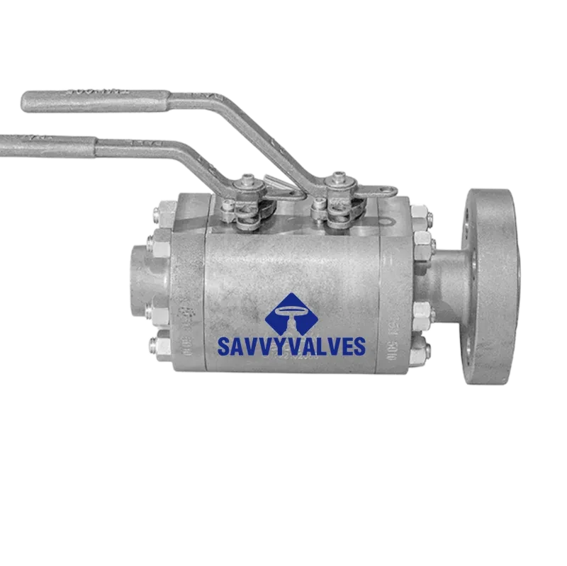
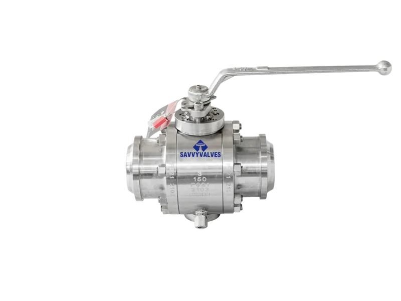
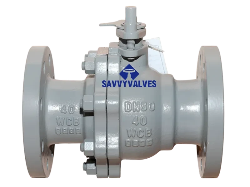
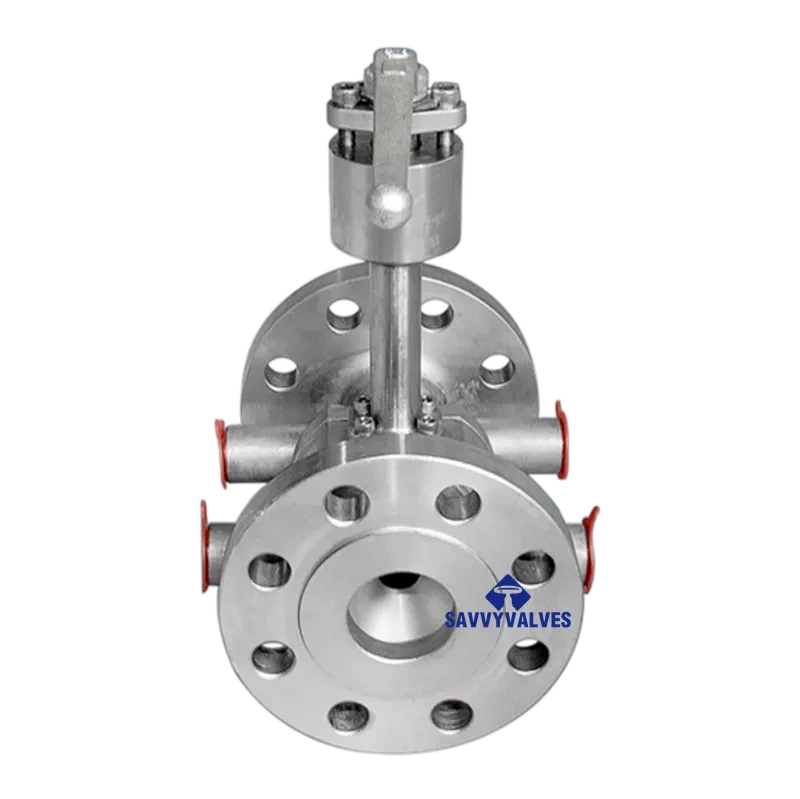
This technical data sheet covers the API 6A, 10,000 PSI floating ball valve, designed specifically for integration with Grayloc hubs. The floating ball design relies on the downstream seat to seal as the ball is pushed against it under line pressure. This valve is suitable for moderate-sized, high‑pressure oil & gas applications including wellhead equipment, manifold systems, and process lines, particularly where compact design and bidirectional sealing are required.
パラメータ | 仕様 |
Product Name | API 6A Floating Ball Valve |
Design Standard | API 6A / ISO 10423 (21st Edition) |
Size Range | 1/2″ to 4″ (larger sizes limited by floating principle) |
Pressure Class | 2,000 psi to 10,000 psi (data sheet focus: 10,000 psi) |
Temperature Class | Class K (-60°C to +82°C) to Class U/V (up to +180°C) |
Product Specification Level (PSL) | PSL 1, PSL 2, PSL 3, PSL 3G (typical: PSL 3G) |
Performance Requirement (PR) | PR 1 (standard) / PR 2 (high‑cycle) |
Material Class | AA, BB, CC, DD, EE, FF, HH (sour service: FF) |
ボアタイプ | Full bore (standard) or reduced bore |
ボディ構造 | 2‑piece or 3‑piece bolted / forged steel |
手術 | Lever, manual gear, pneumatic, electric, hydraulic |
The valve is supplied with integral hubs suitable for Grayloc clamp‑type connectors.
パラメータ | 仕様 |
Connection Type | Grayloc® Clamp Hub Connectors |
Design Pressure | Full vacuum up to 60,000 psig (system rated for 10,000 psi) |
Design Temperature | -423°F to 1,700°F (-253°C to 927°C) |
Sealing Mechanism | Metal‑to‑metal bore seal |
Key Advantages | High‑integrity sealing; weight & space savings vs. RTJ flanges (up to 70% less torque) |
Applicable Standards | Designed per ASME Section VIII, API 6A; optional ASME certification |
Grayloc Hub Interface Note: Hubs are manufactured per Grayloc standards and can be customized for blind, reduced port, or instrument connections. The floating ball valve’s low torque requirement makes it especially compatible with clamp‑type connections.
All materials comply with NACE MR0175 / ISO 15156 for H₂S & CO₂ service.
Component | Standard Material (Sour Service) | Optional Materials |
Body / Bonnet | ASTM A694 F60 / F65, AISI 4130 | A182 F22 (Cr‑Mo), A182 F316 (SS), Duplex SS, Inconel 625 |
ボール | 17‑4PH SS + coating / hardfacing (e.g., NiCr, CrN) | Inconel 625 + Stellite 6, Tungsten Carbide (HVOF) |
シート | Reinforced PTFE, PEEK, Nylon | Devlon, Metal‑to‑Metal (graphite‑filled) |
幹 | 17‑4PH SS / AISI 4140 | Inconel 625, Monel |
Bolting / Fasteners | ASTM A193 B7 / A320 L7 (PTFE coated) | Stainless steel (A193 B8M) |
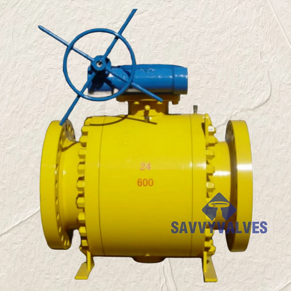
Note on 10,000 psi operation: Floating ball valves in API 6A 10K service are typically limited to sizes ≤ 4″ (NPS). For larger bore sizes, a trunnion‑mounted design is recommended.
All testing per API 6A requirements.
Test Type | Requirement / Procedure |
Body Shell Hydrostatic | 1.5 × rated pressure (15,000 psi) – no leakage through pressure boundary |
Seat Hydrostatic (High Pressure) | 1.1 × rated pressure (11,000 psi) – zero leakage (soft seat) |
Seat Gas (Low Pressure) | 80 – 160 psi – bubble‑tight for soft‑seated valves |
Double Block & Bleed (DBB) | As per API 6A – cavity venting capability verified (optional for floating) |
PR2 Performance Validation | High‑cycle / hyperbaric per API 6A Annex F (if required) |
NDE | MPI / LPI / RT per PSL |
火災試験 | API 6FA / API 607 certification |
Inspection Standard | API 598 (Valve Inspection and Test) |
Disclaimer: This technical data sheet is for informational purposes only. Final specifications are subject to project requirements and engineering review. For sizes above 4″ in 10,000 psi class, a trunnion ball valve is recommended.
保証:
SAVVY VALVESは、卓越した製品品質と安心のアフターサービスの提供に尽力しています。当社のバルブは最低12ヶ月の耐用年数を保証しており、その期間中は必要なスペアパーツと詳細なメンテナンスマニュアルを無料でご提供いたします。保証期間中に人為的要因以外の損傷が発生した場合は、無償で部品を交換し、専門的な技術サポートを提供いたします。保証期間終了後は、スペアパーツ代のみご負担いただき、割引メンテナンスサービスは引き続きご利用いただけます。当社の目標は、信頼性の高い品質と包括的なアフターサービスを通じて、お客様の運用コスト削減と生産効率の向上を支援することです。技術的なお問い合わせやメンテナンスのご依頼など、当社の専門チームが迅速に対応し、お客様のバルブシステムが常に最適なパフォーマンスを維持できるよう尽力いたします。




 Japanese
 English
 Arabic
 Azerbaijani
 Czech
 Dutch
 French
 German
 Indonesian
 Italian
 Korean
 Malay
 Persian
 Polish
 Portuguese
 Russian
 Spanish
 Thai
 Vietnamese